LoRa Extended Ranging mode in LR2021
15 Sep 2025
Introduction to LoRa Ranging
LoRa is well known for allowing long range communication at low data-rate. The modulation technique at its hearth is known as Chirp Spread Spectrum: the user data is spread along a chirp which can then be de-spread at the receiver side, allowing it to demodulate data well below the noise floor.
Chirps are also use classically in many radar technology, because the same de-spreading method can be used to get a precise timing location. And so LoRa also proposes to measure the time-of-flight between two devices by sending special packets (called ranging packets), where the content is perfectly known thus allowing a fine timing estimation.
A ranging estimation is done in three steps:
- the “initiator” device sends a ranging request, containing a device address
- the “responder”, the device with the matching address then sends its response precisely two symbols after the request
- The initiator can then estimate the timing of the receiver: the difference with the expected time if there was no propagation delay is twice the time of flight between the two devices.
The standard ranging has been available in all chips except the 127x series. And now with the LR2021 comes a new variant: the extended ranging. It basically consists in sending a second exchange, with a different chirp configuration. This allows to remove (and estimate) bias which can be created by frequency variation on the devices, induced by the speed of the devices or even local temperature change which occurs when the chip changes being TX and RX. This means that this new ranging mode not only improves the ranging accuracy but also provides a relative speed estimation.
The accuracy will vary with the SNR (Signal-to-Noise Ratio), the bandwidth, the spreading factor and of course of the multi-path effect of the channel. Higher bandwidth will limit effect of multi-path, but of course as-soon as you are in non-line-of-sight situation, accuracy can drop significantly. In perfect condition, using cable, the accuracy on distance can go below 10cm, but in real-life expect something more along a few meters accuracy when in line-of-sight: considering the range of the technology that’s still more than useful !
LoRa Ranging Demo
The demo application is simple:
- The board can act either as initiator or responder, with a long button press allowing to switch the role.
- The responder is simply in continuous RX and ready to respond to any request given to its address.
- The initiator start sending a quick burst of 4 ranging request every second with a short button press. Pressing the button again will stop the transmission.
Analog front-end configuration
The radio configuration is like any other protocol:
- select the TX/RX path (LF for sub-GHz or HF for 2.4GHz),
- run calibration
- set the TX power and ramp time.
Since we want to do a real-life test and try to see some good performances, let’s use the maximum TX power (+22dBm) and the maximum RX Boost:
    lr2021.set_rf(915_000_000).await.expect("SetRF");
    lr2021.set_rx_path(RxPath::LfPath, RxBoost::Max).await.expect("Setting RX path to LF");
    lr2021.calib_fe(&[]).await.expect("Front-End calibration");
    lr2021.set_tx_params(22, RampTime::Ramp8u).await.expect("SetTxParams");
Base-band configuration
The configuration for ranging includes not only the LoRa modulation settings but also some ranging specific one such as the device/request address, the kind of ranging (extended or not) as well as some calibration delay:
    let modulation = LoraModulationParams::basic(SF, BW);

    lr2021.set_packet_type(PacketType::Ranging).await.expect("Setting packet type");
    lr2021.patch_ranging_rf().await.expect("PatchRangingRf");
    lr2021.set_lora_modulation(&modulation).await.expect("Setting packet type");
    lr2021.set_ranging_dev_addr(ADDR_INI, None).await.expect("SetDevAddr");
    lr2021.set_ranging_req_addr(ADDR_RSP).await.expect("SetReqAddr");
    lr2021.set_ranging_params(true, false, 12).await.expect("SetRangingParams");
    let delay = lr2021.get_ranging_base_delay(&modulation);
    lr2021.set_ranging_txrx_delay(delay).await.expect("SetRangingDelay"); // Value depends on SF, BW and PCB
A few notes on the different methods called:
- The
patch_ranging_rfwith adjust some RF settings to ensure stable measurements. - The argument of
set_ranging_paramsare in order: extended mode, spy mode and number of symbols:- the spy mode allows a device to run timing estimation on a ranging exchange taking place between two other devices. This can allow triangulation.
- The number of symbols controls the duration of the exchange: in theory longer exchange gives higher accuracy but in practice it is not useful to use more than 14-15 symbols. Below 8 symbols accuracy starts to drop sharply.
- The ranging TX/RX delay allows to take into account all delay occurring between the antenna and the chip. Semtech provides some basic delay but this does not take into account effect coming from the component on the board. More over those settings are only for standard mode, I’ll need to see if i can find some basic formula to apply in extended.
Main loop
The main loop need to wait on multiple interrupts:
- Ranging Exchange Valid: this triggers on the initiator when a ranging measure is available
- Ranging Response Done: this triggers on the responder side once the last response of the exchange was sent (there are 2 responses in the extended mode)
- Ranging Request Discarded: this triggers on the responder when it receives a ranging request but with an address not matching its own address. This is mainly used to debug the application.
- Ranging Timeout: this triggers on the initiator side when it does not receive a response after its request.
Here is a simplified version of the loop without the button handling:
    lr2021.set_dio_irq(DioNum::Dio7, Intr::new(IRQ_MASK_RNG_EXCH_VLD|IRQ_MASK_RNG_RESP_DONE|IRQ_MASK_RNG_REQ_DIS|IRQ_MASK_RNG_TIMEOUT)).await.expect("Setting DIO7 as IRQ");
    let rssi_offset = lr2021.get_ranging_rssi_offset().await.expect("GetRngOffset");
    loop {
        match irq.wait_for_rising_edge().await {
            let intr = lr2021.get_and_clear_irq().await.expect("GetIntr")
            // Interrupt handling
            if intr.rng_resp_done() {
                BoardNucleoL476Rg::led_green_set(LedMode::Flash);
            } else if intr.rng_req_dis() {
                BoardNucleoL476Rg::led_red_set(LedMode::Flash);
            } else if intr.rng_timeout() {
                BoardNucleoL476Rg::led_red_set(LedMode::Flash);
            } else if intr.rng_exch_vld()  {
                let result = lr2021.get_ranging_ext_result().await.expect("GetRangingResult");
                let rttof = (result.rng1() + result.rng2()) / 2;
                let doppler = result.rng2() - result.rng1();
                let rssi = state.rssi_offset + result.rssi1() as i16;
                info!("[RX] Raw = {}/{} | RSSI = {}dBm| RTTOF = {}, Doppler = {}",
                    result.rng1(), result.rng2(), rssi, rttof, doppler);
            }
            // On initiator side send a packet after 1000ms
            if state.initiator && (intr.rng_exch_vld() || intr.rng_timeout()) {
                Timer::after_millis(1000).await;
                lr2021.set_tx(0).await.expect("SetTx");
            }
        }
    }
The conversion of the round-trip time-of-flight to a distance in meter is simply given by rttof * c / 2 / 4096 / Bandwidth where c is the speed of light m/s.
The Doppler effect conversion to speed in km/h is a little more complicated: doppler * Bandwidth / 2^SF * c/2*3.6 / 4096 / RF.
Note: the final application is available on github. The main loop is actually more complicated, mainly to handle also some button event and to support some extra ranging mode such a burst on button and frequency hopping.
Testing ranging
And now comes the fun part: I’ll have a ride on my bicycle around my home with one device acting as responder, while the initiator is at the window. The condition are far from ideal: I am surrounded by building, and there are many hills so I will likely loose the signals at some point.
Here is the route I will take with some crude drawing showing the different obstacles:
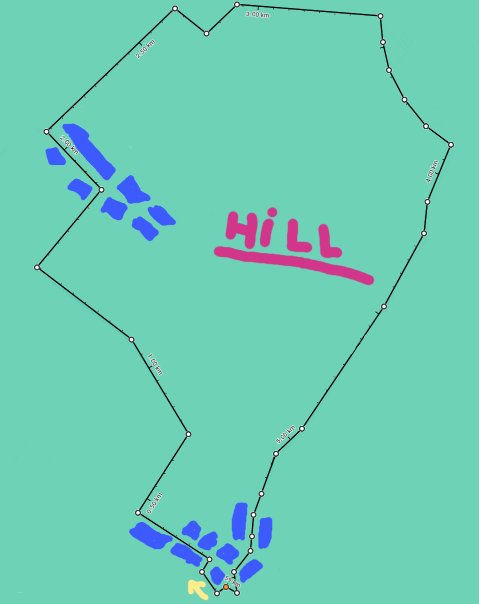
Since I might be at something close to 2km away, I decided to use the spreading factor SF9 with a bandwidth of 250kHz. I thought it would be a good compromise between short exchange and range.
And this is the result (time is given in seconds):
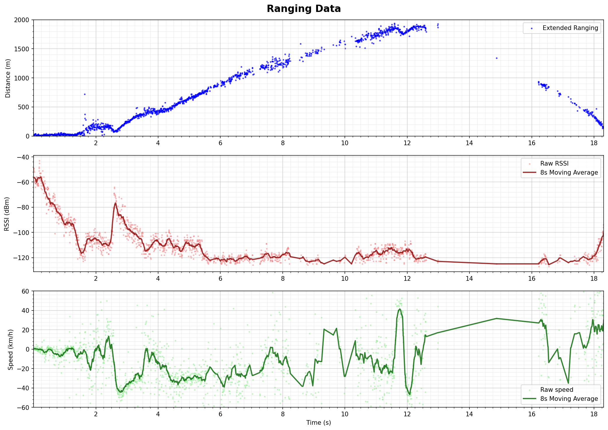
I was lucky on my settings it worked quite well, but clearly I was really hitting the limit: this can be seen with the RSSI reaching quickly the -125dBm, and the link being spotty once I am at more than 1km. And the kink is completely broken when I start coming, but this one I am pretty sure is inevitable due to the terrain. I would need to put the antenna on the roof to have a chance. Still, it is pretty cool to see a range of close to 2km :)
As for the relative speed estimator, it looks not quite noisy, but with the moving average, when the RSSI is not too low, I can clearly recognize what is going on:
- Everything before 1m40 is basically me walking to my bike which is two floor down. I think we can even see the pause when I’m trying to find the key and open the door around 1m.
- Once on my bike, I go away from the house, hence the -15km/h.
- Then I make a turn and starts to get closer until the left turn. This can both be seen at the RSSI sharply increasing (the moment where I an right in line of sight), while the speed goes from positive to negative
- Then I tried to sprint away: the 40km/h might be slightly optimistic :P
- The speed will stays in the negative as long as I am getting farther, which can be verified with the distance.
So even if this relative speed is definitely noisy, this looks usable. One way to improve it could be to correlate it with an estimation of speed simply based on the different distance estimation with the associated timestamp. But anyway this new indicator will always be more noisy simply because this is a more sensitive measure: this is an “instantaneous” speed estimation, meaning things like vibration or just me adjusting my position will affect the measure. The interesting part is that in a standard ranging exchange, this kind of effect would have affected the distance itself: every part where the speed is negative, the standard ranging would have over-estimated the distance, and under-estimated it when the speed is positive.
This was definitely the more sportive wireless demo I did so far, but the results are really nice. I’ll have to try again with different settings to see if I can maintain a stable link along this route :)